
QR Codes on the ZX81
by Andre Leiradella
BackMy first job was as a support analyst at Xerox Brazil for their high-speed printers, the kind that you plug into a Bus and Tag interface to connect to an IBM mainframe. Their use varied from reports and code listings to bank checks and invoices printing.
In Brazil there’s a standardized document that can be used to pay for goods and services called boleto, which is accepted in all banks and ATMs. It uses a barcode called Interleaved 2 of 5, supported by Xerox printers using a special font.
Because boletos were one of biggest motives banks bought printers, my boss made me learn how to decode 2 of 5 barcodes by hand, just by taking note of the width of each bar. I like to think this was important for my profession, but looking back I think it was just a prank.
However, I really liked barcodes, and started to learn about other standards like Code 39 and EAN-13, the later being easy to recognize as they’re printed on the box of every product you can find on the shelves.
Today, I’m mostly interested in 2D barcodes such as Data Matrix (mainly because it’s in the public domain and have a free, open source library that can read and write such barcodes), and QR Codes (because everyone recognizes them and know that they can be scanned, have widespread use, and in my opinion are easy on the eyes).
I keep daydreaming about using barcodes in old computers to achieve augmented technology, where some other, modern hardware can work together with the old one to help it achieve something it cannot on its own. Since the first computer I bought was a ZX81 with the intent of writing games, it’s only natural that I make it able to generate a barcode that can be read by commodity devices such as cellphones.
QR Codes
One-dimension barcodes are usually easy to generate, as they don’t mandate any kind of marks and/or error correction code to be present in the data. Applications using these barcodes would usually employ some simple checksum to prevent erroneous data from entering the system, if any, and it was all ad hoc. Unfortunately, 1D barcodes are not really suitable for a ZX81, since the unmodified hardware had a graphics resolution of 64x48 pixels, with pixels too big to generate barcodes with meaningful data.
Two-dimensions barcodes on the other hand can contain more data, but usually have complex ways to encode the message, and mandate some kind of error correction to be present so that the code can be read even if the barcode is damaged. The maths behind the error correction calculation are way over my head, but one day I was reading the Paged Out! magazine issue 2 and stumbled into an article titled An artisanal QR code where the author shows how to create a QR Code from scratch without any dependencies.
The code is small because it can only generate QR Code version 1, and is hardcoded to ECC (Error Correction Code) level M, and mask 0 (checkerboard). While this may sound too limiting, these allow for up to 14 bytes of data with very little code. Support for all types, ECC levels, and masks would render this project impractical for the humble ZX81, as it’s easy to see here.
With that, I knew I could finally write some Z80 assembly to generate QR Codes.
Preparation
The first thing we’ll do is understand the JavaScript code in the Paged Out! article. It does a good job, except when it starts drawing the QR Code. Thankfully, there are other sources of information that we can use to fill in the blanks.
Message Encoding
The first piece of code is the function that formats the message into the right format for the QR Code.
function to_binary(n) {
    return n.toString(2).padStart(8, "0");
}

function prepare(s, len) {
    // convert s to binary
    var data = s.split('').map(x => to_binary(x.charCodeAt(0)));

    // prepend header
    data.unshift(to_binary(s.length));
    data.unshift("0100");

    // append footer
    data.push("0000")

    var pad = 0xec;

    while ((data.length - 1) < len) {
        data.push(to_binary(pad));
        pad = pad ^ 0xfd;
    }

    // join and split into bytes
    return data.join('').match(/.{8}/g).map(x => parseInt(x, 2));
}

var str = "PagedOut!";
var data = prepare(str, 16);
prepare begins by creating an array of strings data, where each position has a string with the binary representation of the corresponding character in the original message. This array is like a bitstream, where bits can be added at will.
After that, it performs some steps to encode the message:
- Prepend 8 bits with the length of the message
- Prepend
"0100", which means that the message uses binary encoding - Append
"0000", which is the end of message mark - Append alternated binary representations of
0xecand0x11, until the encoded message haslen * 8bits (lenhere is 16, the maximum for this QR Code type)
Example encoded message with "PagedOut!":
| Value | Description |
|---|---|
0b0100 |
Use binary encoding |
| 9 | Message length with 8 bits, maximum value is 14 |
'P' |
Message |
'a' |
|
'g' |
|
'e' |
|
'd' |
|
'O' |
|
'u' |
|
't' |
|
'!' |
|
0b0000 |
End of message mark |
| 0xec | Padding |
| 0x11 | |
| 0xec | |
| 0x11 | |
| 0xec |
With the bits in place, the code then converts the array of bits into an array of bytes and returns it. In this example, the returned array is:
[ 64, 149, 6, 22, 118, 86, 68, 247, 87, 66, 16, 236, 17, 236, 17, 236 ]
The ECC Polynomial
The ECC used in QR Codes is the Reed-Solomon. The theory and math behind it is at least for me very complicated, but we don’t need to understand it. Thankfully, all we need is to use the functions provided in the article.
The code below will generate the ECC polynomial needed to evaluate the error correction code for our QR Code.
// Galois Field multiplication (using Russian
// Peasant Multiplication method)
function gf_mul(x, y, mod) {
    var r = 0;

    while (y>0) {
        if (y & 1) { r ^= x; }

        y >>= 1; x <<= 1;

        if (x > 255) { x ^= mod; }
    }

    return r;
}

function gf_pow(x, n, mod) {
    var r = 1;

    for (var i=0; i<n; i++) {
        r = gf_mul(r, x, mod);
    }

    return r;
}

function polynomial_mul(p, q, mod) {
    var r = [];
    for (var i=0; i<p.length; i++) {
        for (var j=0; j<q.length; j++) {
            r[i + j] ^= gf_mul(p[i], q[j], mod);
        }
    }
    return r;
}

function get_generator_poly(n) {
    var g = [1];

    for (var i=0; i<n; i++) {
        g = polynomial_mul(g, [1, gf_pow(2, i, 285)], 285);
    }

    return g;
}

var generator_poly = get_generator_poly(10);
Instead of using all that code to create generator_poly, we’ll hardcode the resulting 11-bytes polynomial in our code since it’ll save us precious bytes in the ZX81, and any other Z80-based computer:
[ 1, 216, 194, 159, 111, 199, 94, 95, 113, 157, 193 ]
The ECC
With the generator polynomial in our hands, the following code will compute the ECC for any given message.
function polynomial_mod(a, b, mod) {
    var n = a.length - b.length + 1;

    while (b.length < a.length) {
        b.push(0);
    }

    for (var i=0; i<n; i++) {
        var f = a[0];

        for (var j=0; j<b.length; j++) {
            a[j] = a[j] ^ gf_mul(b[j], f, mod);
        }

        a.shift();
        b.pop();
    }

    return a;
}

var ecc = polynomial_mod(
    data.concat(new Array(10)),
    generator_poly,
    285
);
It’s easier to understand what it does if we take a look at the equivalent C code.
// Polynomial modulus.
static void qrc1_polymod(uint8_t* const a,
                         size_t const lena,
                         uint8_t const* const b,
                         size_t const lenb,
                         uint16_t const mod) {

    // Zero the part of A that will contain the modulus.
    memset(a + lena, 0, lenb - 1);
    size_t const maxlena = lena + lenb - 1;

    // Perform the modulus.
    for (size_t i = 0; i < lena; i++) {
        uint8_t const f = a[i];

        for (size_t j = 0; j < (maxlena - i); j++) {
            a[i + j] ^= qrc1_gfmul(j < lenb ? b[j] : 0, f, mod);
        }
    }
}

// The encoded message always has 16 bytes, and the generator
// always has 11 bytes. msg must have 26 bytes to
qrc1_polymod(msg, 16, generator, 11, 285);
The result is computed at the end of a, so we zero 10 bytes starting at a + lena. Because of that, a must have 26 bytes, which is the exact size of the payload that this QR Code supports, with the encoded message and it’s ECC.
The for loops will then iterate over the polynomials and do their magic. It’s important to notice that qrc1_polymod destroys the original message, so we have to have a copy somewhere before calling it.
The Format Information
I said above that the QR Code that we’ll generate is hardcoded to ECC level M, and mask 0. This information must be present somewhere in the QR Code so that barcode readers know how to decode it. The format info is a sequence of 5 bits that contain this information:
- Two bits for the ECC level (
0b00for level M) - Three bits for the mask index (
0b000for mask 0)
The format info has some error correction code of its own, and the resulting sequence is xor’ed with a predefined sequence of bits to give the final 15-bits sequence that goes into the QR Code.
var format = [0, 0, 0, 0, 0];
var format_info = format.concat(
    polynomial_mod(
        format.concat(new Array(10)),
        [1,0,1,0,0,1,1,0,1,1,1],
        1335
    )
);

var mask = [1,0,1,0,1,0,0,0,0,0,1,0,0,1,0];

for (var i=0; i<format_info.length; i++) {
    format_info[i] ^= mask[i];
}
Since the format info is always the same in our case, we’ll hardcode its value with the ECC already appended and the mask bits already xor’ed to save some bytes:
[ 1, 0, 1, 0, 1, 0, 0, 0, 0, 0, 1, 0, 0, 1, 0 ]
Drawing
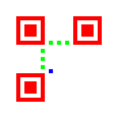
The QR Code version 1 has 21x21 pixel (modules if we use its terminology), some of which are fixed and must be present regardless of the encoded message and format info.
Starting with a blank 21x21 canvas, the three finders patterns (in red below) must be drawn, along with the timing patterns (in green), and the “dark” module (in blue).
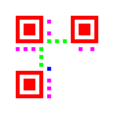
On top of this QR Code template we draw the format info and the encoded message. However, since our format info is hardcoded, we can draw it as part of the fixed pixels (in magenta).
Now the only thing missing is the encoded message with its ECC. To draw it, we must follow a zigzag pattern starting at the bottom-right pixel and going up to the format info, then go to the left and continuing down up to the border, then up again until we draw all the bits from the encoded message, like in the image below.
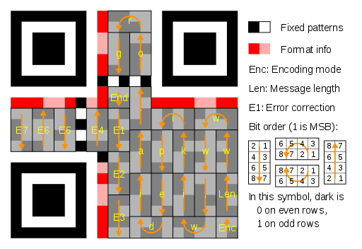
It’s possible to notice the four bits for the encoding type (Enc), the eight bits with the length of the message (Len), then the message contents (www.wikipedia.org in the example image), the end of message mark (End), and the ECC bytes (E1 to E7). In our case, we have 10 bytes of ECC, but the zigzag pattern is exactly the same.
Every time we draw a pixel, a mask must be applied. The purpose of the mask is to increase the odds that the QR Code will be successfully decoded by trying to avoid patterns in the code that look like the finders patterns, and by balancing the amount of black and white pixels.
The process of finding the best mask to use with a particular payload is not complicated but, would greatly increase the size of the program, so we hardcode the checkerboard mask.
Since drawing depends on the device, we’ll see how the QR Code is drawn onto the ZX81 screen later.
Translating to Z80 Asm
Before translating the code to assembly, we have to think about how we want the program to work. Instead of having a ZX81 program that always shows the same QR Code, we’ll write a program that asks the user for the message, then encodes it and draws the QR Code onto the screen, and then goes back to the first step.
Instead of using machine code exclusively, we’ll use BASIC for everything except the encoding and drawing. The program is this:
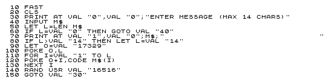
Some magic numbers present in the program come from the machine code side: 17329 is where we put the message length, and the message characters following it, and 16516 is where the machine code routine that encodes and draws the QR Code starts. The many VAL functions used in the code are there because the BASIC code is generated by the assembly file, and it’s easier to generate number constants that way than encoding them using the ZX81 proprietary floating point format.
With that part behind us, lets take care of the assembly.
ASCII Translation
Before encoding the message, we must translate the characters from the proprietary encoding used in the ZX81 to ASCII. This is done via a simple loop that takes a ZX81 character, uses it’s value to index a table, and gets the ASCII character from that table.
to_ascii:
    ; Make HL point to the unencoded message.
    ld hl, qrc1_message

    ; B has the message length.
    ld b, (hl)
    inc hl

xlate_loop:
        ; Put the ZX81 character in A, making sure it's valid and non-inverted.
        ld a, (hl)
        and $3f

        ; Get the corresponding ASCII character in the translation table.
        add a, xlate_table & $ff
        ld e, a
        ld a, 0
        adc a, xlate_table >> 8
        ld d, a
        ld a, (de)

        ; Overwrite with the ASCII char.
        ld (hl), a
        inc hl
    djnz xlate_loop
    ret

xlate_table:
    ;  spc  gra  gra  gra  gra  gra  gra  gra  gra  gra  gra   "    £    $    :    ?
    db ' ', '?', '?', '?', '?', '?', '?', '?', '?', '?', '?', '"', '?', '$', ':', '?'

    ;   (    )    >    <    =    +    -    *    /    ;    ,    .    0    1    2    3
    db '(', ')', '>', '<', '=', '+', '-', '*', '/', ';', ',', '.', '0', '1', '2', '3'

    ;   4    5    6    7    8    9    A    B    C    D    E    F    G    H    I    J
    db '4', '5', '6', '7', '8', '9', 'A', 'B', 'C', 'D', 'E', 'F', 'G', 'H', 'I', 'J'

    ;   K    L    M    N    O    P    Q    R    S    T    U    V    W    X    Y    Z
    db 'K', 'L', 'M', 'N', 'O', 'P', 'Q', 'R', 'S', 'T', 'U', 'V', 'W', 'X', 'Y', 'Z'
Some characters that don’t exist in the US-ASCII character set are translated to '?'.
Message Encoding
Now we can encode the message. The qrc1_encmessage subroutine that does this begins with
; qrc1_message contains the message length followed by the message (from 1 to
; 14 bytes).
qrc1_encmessage:
meaning that it expects the message length in the byte at qrc1_message, followed by the message bytes. The message is encoded in-place and will be destroyed in the process.
First we take care of the type of data and the high nibble of the message length, which will always be 0.
    ; Use byte encoding (0b0100 << 4), length high nibble is always 0 since
    ; len <= 14.
    ld hl, qrc1_message
    ld a, (hl)
    ld (hl), $40
    inc hl
We then shift the entire message right by four bits, inserting the low nibble of the message length that is in A at the beginning of the encoded message.
    ; Save message length for later for the padding.
    ld c, a

    ; Shift the message to the right by four bits.
    ld b, a
qrc1_shift_msg:
        rrd
        inc hl
    djnz qrc1_shift_msg

    ; A has the low nibble of the last message byte, shift it to the high
    ; nibble and set the low nibble to 0, which is the end of message mark.
    ld (hl), 0
    rrd
    inc hl
The rrd instruction makes it easy to shift the message four bytes to the right, which is all we have to do to open up space for the encoding type at the beginning of the encoded bits. The last rrd ensures that the low four bits of the last message byte and the end of message mark are appended to the encoded message.
With the message shifted, we can pad it with 0xec and 0x11 until the encoded message has 16 bytes in total.
    ; HL points to the byte of the message that has the end of message mark,
    ; save it for later.
    push hl

    ; Pad the rest of the message with $ec and $11.
    ld a, 14
    sub c
    jr z, qrc1_no_padding

    ld b, a
    ld a, $ec
qrc1_pad_msg:
        ld (hl), a
        inc hl
        xor $fd
    djnz qrc1_pad_msg

qrc1_no_padding:
All done, the message is encoded and we’re ready to evaluate the ECC.
Since the ECC evaluation will destroy the message, we start by saving it to a scratch area so we can retrieve it later. We also zero the 10 bytes of the ECC that come after the encoded message to prepare it for the evaluation.
    ; Copy the original encoded message to the scratch buffer, the ECC
    ; evaluation will overwrite it so we need to restore it at the end.
    ld hl, qrc1_message
    ld de, qrc1_scratch
    ld bc, 16
    ldir

    ; Zero the 10 bytes where the ECC will be stored.
    xor a
    ld b, 10
qrc1_zero_ecc:
        ld (hl), a
        inc hl
    djnz qrc1_zero_ecc
To compute the ECC we have to iterate over the encoded message in an outer loop, while we iterate over the generator polynomial for the ECC in an inner loop. The outer loop iterates over the encoded message, while the inner loop iterates over both the encoded message and the generator polynomial.
We then need two pointers for the polynomials, and two 8-bit counters for the loops. We’ll use HL for the first polynomial, the encoded message, and DE for the second, the generator. For the loop counters we’ll use IYL and IYH, since we’ll need many registers in the meat of the inner loop.
    ; HL is the polynomial A.
    ld hl, qrc1_message

    ; IYL is the outer loop counter (i) for the length of A.
    ld iyl, 16
qrc1_loop_i:
        ; Save HL as it'll be incremented in the inner loop.
        push hl

        ; Save A[i] in B to be used inside the inner loop.
        ld b, (hl)

        ; DE is the polynomial B.
        ld de, qrc1_ecc_poly

        ; Evaluate the inner loop count limit.
        ld a, 11
        add iyl
        dec a

        ; IYH is inner loop counter (j) up to length(A) - i.
        ld iyh, a
qrc1_loop_j:
Now we put the needed values in the registers and evaluate the Galois Field multiplication. The C algorithm below will help understanding the assembly code.
// Galois Field multiplication.
static uint8_t qrc1_gfmul(uint16_t x, uint8_t y, uint16_t const mod) {
    uint8_t r = 0;

    while (y != 0) {
        if (y & 1) {
            r ^= (uint8_t)x;
        }

        y >>= 1;
        x <<= 1;

        if (x > 255) {
            x ^= mod;
        }
    }

    return r;
}
The register A is x in the C code, D is y, mod is hardcoded to 285, and E is r. We use C as a scratch register. Everything is set up below (remember we saved A[i] in B before we enter the inner loop).
            ; A is B[j]
            ld a, (de)

            ; Save DE as we'll use D and E in the gf_mod loop.
            push de

            ; D is A[i], E is the gf_mod result.
            ld d, b
            ld e, 0

            ; A is x, D is y, E is r, C is a scratch register (gf_mul).
With everything set up, we can do the multiplication. We start by jumping to the end, where we do the test for the while loop as follows:
Dis shifted right- If
Dhad the low bit set,Eis xor’ed withA,Ais updated, and we test the loop condition again - If
Dis not zero,Ais updated, and we test the loop condition again - If
Dis zero, the multiplication loop ends
To update A we shift it left, and xor it with 285 if its high bit was set.
            jr qrc1_test_y

qrc1_xor_res:
                ; y had the 0th bit set, r ^= x.
                ld c, a
                xor e
                ld e, a
                ld a, c
qrc1_dont_xor:
                ; x <<= 1, carry set if x >= 256.
                add a, a
                jr nc, qrc1_test_y

                    ; x was >= 256, xor it with the module.
                    xor 285 & $ff
qrc1_test_y:
                ; y >>= 1, update r if the 0th bit is set, end the loop if
                ; it's zero.
                srl d
                jr c, qrc1_xor_res
                jr nz, qrc1_dont_xor
When the loop ends, E has the result for the current inner loop operation, which we then xor with the polynomial A. We then restore DE (we had to use D and E in the multiplication), increment it and HL to the next bytes in the polynomials, and test for the end of the inner loop.
            ; A[i + j] ^= gf_mod(...)
            ld a, (hl)
            xor e
            ld (hl), a

            ; Restore DE.
            pop de

            ; Update HL and DE to point to the next bytes of A and B.
            inc hl
            inc de

        ; Inner loop test.
        dec iyh
        jr nz, qrc1_loop_j
When the inner loop exits, we restore HL (since it was incremented in every inner loop iteration), increment it to the next byte of the A polynomial, and test for the end of the outer loop. When the outer loop exits, we restore the encoded message that was erased during ECC calculation.
        ; Restore HL since it was changed in the inner loop, and make it point
        ; to the next byte in A.
        pop hl
        inc hl

    ; Outer loop test.
    dec iyl
    jr nz, qrc1_loop_i

    ; Restore the original encoded message, since the loops above zero it.
    ld hl, qrc1_scratch
    ld de, qrc1_message
    ld bc, 16
    ldir
Applying the Mask
With the ECC in place, we apply the checkerboard mask over the encoded message.
To apply the mask, for every bit in the encoded message and ECC, we have to test the corresponding pixel coordinates using a condition that depends on the used mask, and invert the bit if the condition is true. Only after that we test the bit and set the corresponding pixel if it’s 1.
Instead of applying the mask when drawing, we pre-apply the mask on top of the encoded message and the ECC, because it’s easier to have the hardcoded bit pattern of the mask than to test each pixel for the mask condition when drawing.
If we follow the zigzag pattern to draw the modules and test for the mask 0 condition where (x + y) % 2 must be zero, we end up with the following values:
0x99, 0x99, 0x99, 0x66, 0x66, 0x66, 0x99, 0x99,
0x99, 0x66, 0x66, 0x66, 0x99, 0x99, 0x99, 0x96,
0x66, 0x99, 0x96, 0x66, 0x66, 0x66, 0x99, 0x99,
0x66, 0x99
However, the encoding type and the end of message mark must not be masked, so their corresponding positions in the mask must be zeroed. The encoding type is always the first four bits of the encoded mask, so we change the first byte from 0x99 to 0x09. To zero the end of message mark in the mask, which depends on the message length, we use the value of HL that we saved before evaluating the ECC, right before padding the message with 0xec and 0x11.
To change the mask we first copy it to the scratch buffer, so that we can use it again in a subsequent encoding. After the copy, we use HL to get the position of the end of message mark and zero the low nibble.
To apply the mask we just xor the encoded message and ECC with the patched mask.
    ; Copy the checkerboard mask to the scratch buffer.
    ld hl, qrc1_encmessage_mask_0
    ld de, qrc1_scratch
    ld bc, 26
    ldir

    ; Restore the pointer to the last message byte.
    pop hl

    ; Add the offset from the scratch buffer that contains the mask to the
    ; message to point to the corresponding byte in the mask, HL will point to
    ; the byte in the mask that corresponds to the end of message mark in the encoded message.
    ld de, qrc1_scratch - qrc1_message - 1
    add hl, de

    ; Clear the bits in the mask that correspond to the end of message mark.
    ld a, (hl)
    and $f0
    ld (hl), a

    ; Xor the mask with the encoded message.
    ld hl, qrc1_message
    ld de, qrc1_scratch
    ld b, 26
qrc1_xor_mask:
        ld a, (de)
        xor (hl)
        ld (hl), a
        inc hl
        inc de
    djnz qrc1_xor_mask
    ret
When this routine ends, qrc1_message contains the encoded message along with its ECC, already masked with the checkerboard mask. All that is left to do is draw the QR Code.
Drawing
Screen Cursor
To draw the QR Code we’ll need to read its bits one by one, as each one corresponds to a pixel. Each bit read will tell if the corresponding pixel must be set (turned black) or kept reset (stay white).
Before diving into the details, it’s important that we know how the ZX81 screen works. The ZX81 only features a 24x32 characters, text mode screen, although it’s possible to write custom video generation routines to achieve pseudo-high resolutions with unmodified hardware.
In the standard mode, there are 64 different characters and their inverses, using a proprietary encoding. Among those characters there are the block graphic characters with values from 0 to 7 and from 128 to 135, which subdivides the character into a 2x2 grid, making it possible to draw graphics with a resolution of 64x48 pixels.
Unfortunately, the bit pattern of the character codes doesn’t follow the visual representation of the character on the screen. For characters from 0 to 7 there’s a direct relationship of bits 0 to 2 where bit 0 corresponds to the top-left pixel in the character, bit 1 to the top-right, and bit 2 to the bottom-left. However, bit 3 doesn’t correspond to the bottom-right pixel, if we want to set this pixel in the character we will have to convert the character to the inverted characters since all block graphic characters with this pixel set are inverted characters.
To correctly set the bottom-right pixel, it’s necessary to convert the character to a different representation where bits 0 to 3 correspond to the pixels in the character, set it, and then convert back to the resulting character.
It’s not that difficult, really. If the character has the 7th bit set, it’s an inverted character, so we can xor its code with 0x8f to bring the values in the 135->128 range to 8->15. Then we can set/reset the bits from 0 to 3 at will, and when we’re done we convert it back to a character by checking bit 4: if it’s set, we xor the value with 0x8f again to bring values in the 8->15 range back to 135->128. Note that this only works if we can be sure that we’ll only be dealing with block graphic characters.
Now that we know how to set and reset individual pixels inside a character, we can implement a screen cursor. That cursor must support operations to move up, down, left, and right, and to set the current pixel. We don’t need to reset the current pixel, since we’ll make sure all of them are white before start drawing.
The screen cursor uses DE to point to the corresponding character in the screen, and C to tell which pixel in the character corresponds to the module:
- 1: The pixel is in the top-left position in the character
- 2: The pixel is in the top-right position
- 4: The pixel is in the bottom-left position
- 8: The pixel is in the bottom-right position
We then write routines to move the cursor in the four directions, and to set the pixel for the current cursor position. Depending on the value of C only it has to be updated when moving the cursor, but sometimes the DE must also be updated because the next pixel is in a different character.
; Moves the cursor one pixel to the left.
pixel_left:
    ; 1 -> 2 | 0001 -> 0010, top-left to top-right, decrement de
    ; 4 -> 8 | 0100 -> 1000, bottom-left to bottom-right, decrement de
    ; 2 -> 1 | 0010 -> 0001, top-right to top-left, de is unchanged
    ; 8 -> 4 | 1000 -> 0100, bottom-right to bottom-left, de is unchanged
    ld a, 5
    and c
    jr z, dont_dec
        sla c
        dec de
        ret
dont_dec:
    srl c
    ret

; Moves the cursor one pixel to the right.
pixel_right:
    ; 1 -> 2 | 0001 -> 0010, top-left to top-right, de is unchanged
    ; 4 -> 8 | 0100 -> 1000, bottom-left to bottom-right, de is unchanged
    ; 2 -> 1 | 0010 -> 0001, top-right to top-left, increment de
    ; 8 -> 4 | 1000 -> 0100, bottom-right to bottom-left, increment de
    ld a, 5
    and c
    jr nz, dont_inc
        srl c
        inc de
        ret
dont_inc:
    sla c
    ret

; Moves the cursor one pixel up.
pixel_up:
    ; 1 -> 4 | 0001 -> 0100, top-left to bottom-left, subtract 33 from de
    ; 2 -> 8 | 0010 -> 1000, top-right to bottom-right, subtract 33 from de
    ; 4 -> 1 | 0100 -> 0001, bottom-left to top-left, de is unchanged
    ; 8 -> 2 | 1000 -> 0010, bottom-right to top-right, de is unchanged
    ld a, 3
    and c
    jr z, dont_sub
        sla c
        sla c
        ld a, e
        sub 33
        ld e, a
        ld a, d
        sbc 0
        ld d, a
        ret
dont_sub:
    srl c
    srl c
    ret

; Moves the cursor one pixel down.
pixel_down:
    ; 1 -> 4 | 0001 -> 0100, top-left to bottom-left, de is unchanged
    ; 2 -> 8 | 0010 -> 1000, top-right to bottom-right, de is unchanged
    ; 4 -> 1 | 0100 -> 0001, bottom-left, to top-left, add 33 to de
    ; 8 -> 2 | 1000 -> 0010, bottom-right to top-right, add 33 to de
    ld a, 3
    and c
    jr nz, dont_add
        srl c
        srl c
        ld a, e
        add 33
        ld e, a
        ld a, d
        adc 0
        ld d, a
        ret
dont_add:
    sla c
    sla c
    ret

set_pixel:
    ld a, (de)
    bit 7, a
    jr z, invert1
        xor $8f
invert1:
    or c
    bit 3, a
    jr z, invert2
        xor $8f
invert2:
    ld (de), a
    ret
Bitstream
To decide which pixel must be set or reset, we must read the encoded message as a bitstream. We’ll use HL to point to the current byte of the message, and B to tell which is the current bit. Since testing bits of the bitstream is equivalent to setting (or not) pixels on the screen, we can combine the two and write a routine that tests the current bit, sets the pixel if it was 1, and moves the bitstream to the next bit.
set_pixel_if:
    ld a, (hl)
    and b
    call nz, set_pixel

    srl b
    ret nz

    inc hl
    ld b, $80
    ret
We can also have some helper routines. When we draw the modules in a zigzag pattern, it’s possible to see that the pattern repeats in groups of two pixels, i.e. when going up:
- Test the current bit and set/reset the pixel
- Move the cursor to the left
- Test the current bit and set/reset the pixel
- Move the cursor up and to the right
- Repeat with the next two bits
Since it’s possible to draw entire nibbles at one time in the QR Code without overwriting prohibited areas, we can expand the group from 2 to 4 pixels.
nibble_up_count:
        call set_pixel_if
        call pixel_left
        call set_pixel_if
        call pixel_up
        call pixel_right
        call set_pixel_if
        call pixel_left
        call set_pixel_if
        call pixel_up
        call pixel_right
    dec iyl
    jr nz, nibble_up_count
    ret

nibble_down_count:
        call set_pixel_if
        call pixel_left
        call set_pixel_if
        call pixel_down
        call pixel_right
        call set_pixel_if
        call pixel_left
        call set_pixel_if
        call pixel_down
        call pixel_right
    dec iyl
    jr nz, nibble_down_count
    ret
These two functions will draw IYL nibbles up or down, taking bits from the encoded message bitstream as they go.
Fixed Modules
Having all the required code in place, we can start drawing the QR Code.
The first thing that we do is to draw the fixed pixel of the QR Code. When we do this, we erase any modules from the previous QR Code, making sure they’re all white so we only have to change them if a bit in the bitstream is 1 and we have to turn the pixel black.
DE is set to the up-left corner of the QR Code in the screen, where it’s nicely centered both horizontally and vertically. We start with DE being 22 bytes less than the actual position, because we want it to be right after the last character put onto the screen at the end of the loop, for reasons that we’ll see below.
We then just copy the graphic characters that form the empty QR Code in a loop using ldir.
print_qrcode:
    ; Put the screen address for the top-left of the QR Code in DE.
    ld hl, ($400c)
    ld de, 33 * 6 + 11 - 22
    add hl, de
    ex de, hl

    ; HL points to the fixed QR Code blocks. Here it also includes the
    ; pre-computed format info.
    ld hl, fixed_modules

    ; 21 rows, but each character is two pixel height, so count to 11.
    ld iyl, 11
draw_fixed_row:
        ; Update DE to the start of the next row; we do this here so that DE
        ; is next to the desired location to start drawing the message blocks.
        ld a, 22
        add e
        ld e, a
        ld a, 0
        adc d
        ld d, a

        ; Transfer the characters.
        ld bc, 11
        ldir
    dec iyl
    jr nz, draw_fixed_row
At the end of the loop, DE is one character to the right of the bottom-right character of the QR Code. We then decrement it and set C to 1, so we have the screen cursor at the bottom-right pixel of the code.
After setting up the screen cursor, we set up HL and B to be our bitstream.
    ; Draw the message and the ECC, DE points to the character just to the
    ; right of the one where drawing starts.
    dec de
    ld c, 1 ; Upper-left pixel

    ; Message bits.
    ld hl, qrc1_message
    ld b, $80 ; Most significant bit
We can now call the functions to draw entire columns of nibbles, and to jump over prohibited areas such as the timing patterns.
    ; Six nibbles up.
    ld iyl, 6
    call nibble_up_count

    ; Update the cursor.
    call pixel_down
    call pixel_left
    call pixel_left

    ; Six nibbles down.
    ld iyl, 6
    call nibble_down_count

    ; Update the cursor.
    call pixel_up
    call pixel_left
    call pixel_left

    ; Six nibbles up.
    ld iyl, 6
    call nibble_up_count

    ; Update the cursor.
    call pixel_down
    call pixel_left
    call pixel_left

    ; Six nibbles down.
    ld iyl, 6
    call nibble_down_count

    ; Update the cursor.
    call pixel_up
    call pixel_left
    call pixel_left

    ; Seven nibbles up.
    ld iyl, 7
    call nibble_up_count

    ; Jump the timing marks.
    call pixel_up

    ; More three nibbles up.
    ld iyl, 3
    call nibble_up_count

    ; Update the cursor.
    call pixel_down
    call pixel_left
    call pixel_left

    ; Three nibbles down.
    ld iyl, 3
    call nibble_down_count

    ; Jump the timing marks.
    call pixel_down

    ; Seven nibbles down.
    ld iyl, 7
    call nibble_down_count

    ; Update the cursor, two pixels to the left, nine pixels up.
    call pixel_left
    call pixel_left

    ld iyl, 9
loop_up8:
        call pixel_up
    dec iyl
    jr nz, loop_up8

    ; Two nibbles up.
    ld iyl, 2
    call nibble_up_count

    ; Update the cursor, jump the timing marks.
    call pixel_left
    call pixel_left
    call pixel_left
    call pixel_down

    ; Two nibbles down.
    ld iyl, 2
    call nibble_down_count

    ; Update the cursor.
    call pixel_left
    call pixel_left
    call pixel_up

    ; Two nibbles up.
    ld iyl, 2
    call nibble_up_count

    ; Update the cursor.
    call pixel_left
    call pixel_left
    call pixel_down

    ; Two nibbles down.
    ld iyl, 2
    call nibble_down_count

    ; Done.
    ret
When the routine returns, the QR Code is ready to be scanned.
Uses
There aren’t many uses of a QR Code generator for the ZX81, but some kind of augmented technology, where we can use some external hardware to read the QR Code and do something that is difficult for the ZX81 like downloading something from the Internet and sending the data to the ZX81 via some interface or even using the cassette input in unmodified hardware, opens up some interesting possibilities:
- Implement games and applications much bigger than the original hardware allows
- Send high scores from a game to a server, like how Nogalious does using a mobile app that can read a barcode generated in the game
Source Code
The code presented here is available in a GitHub repository. If you use it in a project, I’d love to know.
The assembly code that encodes the message, calculates the ECC, and applies the checkerboard mask are isolated from the ZX81 specific code, so it should be easy to generate QR Codes in other machines by writing just the platform specific code to draw the code onto the screen.
Back